FroboMind Robot:Frobit:Electronics
Power supply
Motor controller
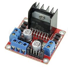
The motor controller typically used for the Frobit is a dual H-bridge module based on the L298N chip. The Dual H-bridge is available from China at ebay and typcially cost about $4.

Serial communication
EXT port to Bluesmirf bluetooth module
Signal             Port
TX-O               10
RX-I               12
VCC                1
GND                11
EXT port to FTDI cable
Signal             Port
TX                 10
RX                 12
GND                11
Motor control
Dual H-bridge connections
Signal             Port  Color
Motor left EN      PD6
Motor left C       PD3
Motor left D       PB5
Motor right EN     PD5
Motor right C      PB3
Motor right D      PB2
Encoder feedback
Motor connections
Signal             Port  Color
Encoder left A     PB4   Blue
Encoder left B     PB1   Purple
Encoder right A    PC4   Blue
Encoder right B    PC5   Purple
Voltage measurement
The RoboCard continuously measures the voltage of the Frobit battery. The measurement is outputted through the Frobit Status message. The measurement circuit is a voltage divider between the Frobit Battery and GND, and the voltage divider output is measured using ADC0. The value transmitted is the raw output from the ADC to allow external calibration of the voltage divider measurements. The value range is [0;1023] corresponding to 0-5V on the voltage divider output.
To protect the RoboCard ADC from overvoltage a 4.7V zener diode is inserted in parallel with the smaller resistor. This ruins the linearity of the voltage divider as the zener diode has a leak current that increases the closer the voltage gets to the nominal rating of the diode. Therefore to convert the ADC output to a proper voltage, a 2. degree polynomium fitted to the output values is needed. For more information on this please see this documentation.